Selling since 1984 
No products
Product successfully added to your shopping cart
There are 0 items in your cart. There is 1 item in your cart.
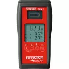
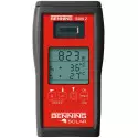
Installation tester for photovoltaic systems and curve tracer BENNING PV 2 BENNING PV 2
 View larger

")
Benning PV 2 short description of measuring functions
possibility of performing following measurements:
- measurement of continuity of protective conductors and equipotential bonding 200 mA
- insulation measurement with testing voltages of 250 V
- insulation measurement with testing voltages of 500 V
- insulation measurement with testing voltages of 1000 V
- voltage measurement without solar load
- short circuit current measurement of solar installation
- measurement of solar load current
Features and functions of the Benning PV 2 meter:
- clear and unambiguous display of all measurement results
-safe measurement connection, even if the photovoltaic system is delivering energy
- automatic test procedures for curve measurement with or without RISO testing
- indication of Uo/c, Umpp, Is/c, Impp, filling factor (FF) and RISO with “PASS/FAIL” indication
- insulation measurement with testing voltages of 250 V, 500 V and 1000 V
- separate insulating resistance measurement via 4mm measuring leads for tests of PV cables etc
- automatic testing procedure (open-circuit voltage 1000 V DC, short-circuit current 15 A DC, insulating resistance)
- automatic display of voltage polarity with audio/ visual warning for reverse polarity
- null balance of the measuring leads
- measured values memory for 999 display indications (PV strings)
- USB interface and download software BENNING SOLAR Datalogger for downloading measured values in CSV format
- equipped with an integrated real-time clock which automatically adds a date / time stamp to each storage process or storage location
- Radio connection to the optional insolation and temperature measuring instrument BENNING SUN 2
- download software for the preparation of test certificates in MS Excel
- ISO measuring result with “pass / fail” information
-direct connection to all standard photovoltaic modules with MC4 or „Sunclix“ connectors
- easy operation for network-indepedently and mobile testing
- LC display with background lightning
- automatic switch-off (individually adjustable from 1 to 10 minutes)
- tests can refer to PV modules, PV strings or the entire PV system
- optional PC software BENNING SOLAR Manager (item no. 050423) for the creation of test reports and documentation of characteristics
- free app BENNING PV Link (requires Android device with NFC)
| BENNING PV 2 | |
| indication | graphic display (illuminated) |
| protective conductor resistance | 0.05 Ω – 199 Ω |
| testing current | ± 200 mADC |
| open circuit voltage (Uo/c) | 5 V – 1000 VDC |
| short-circuit current (Is/c) | 0.5 A – 15 ADC |
| insulation resistance (Riso) | 0.2 MΩ – 199 MΩ |
| testing voltage | 250 V, 500 V, 1000 VDC |
| insulation resistance (2-pin) | 0.05 MΩ – 300 MΩ |
| AUTO measurement 1 | +/-, Uo/c, Is/c, Riso |
| AUTO measurement 2 | Characteristic (I-V, P-V) |
| AUTO measurement 3 | Measurement 1 + 2 |
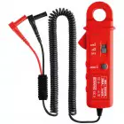
| DC string current/AC current | 0.1 A – 40 AAC/DC (by means of BENNING CC 3) |
| insolation | 100 W/m2 - 1250 W/m2 (by means of BENNING SUN 2) |
| PV module/ambient temperature | - 30 °C - + 125 °C (by means of BENNING SUN 2) |
| voltage (2-pin) | 30 V - 440 V AC/DC |
| measured value memory | 999 data record |
| interface | USB/radio/NFC |
| scope of delivery | Carrying case, measuring leads, crocodile clips, MC4 and sunclix measuring leads, batteries, USB cable, CD-ROM with download-software, calibration certificate |


Control and display elements:
- Digital display shows the test progress and the results of individual measurements
- RPE button, protective conductor resistance testing
- Auto button, runs the automatic PV test procedure in accordance with VDE 0126-23 (DIN EN 62446)
- Riso button, insulation resistance testing (2-pin)
- Mode button, selection of test procedure
- NULL button for zeroing the measuring line resistance
- V ISO button, selection of test voltage for measuring insulation resistance
- NFC sensor for transferring data to an Android device
- Recall saved readings (display values)
- USB interface (micro-B socket), for connecting a USB connection cable
- Recalling saved readings (displayed values)
- LCD display switching
- Saving the displayed measured values (displayed values)
- + PV test socket (red), for connecting the red test lead with a PV plug connector
- - PV test socket (black), for connecting the black test lead with a PV plug connector
- - 4 mm test socket (black), for connecting a safety test lead with a crocodile clip / probe
- + 4mm test socket (red), for connecting a safety test lead with a crocodile clip / probe
A - RPE The voltage polarization indicator shows the polarity of the direct current on the 4 mm 15 and 16 test sockets. Alternating voltage displays alternating "+" and "-".
B - Active measurement of current clamps
C - NULL RPE (Null-Offset), appears with compensation (zero correction) of the measuring line resistance.
D -(Caution, hot surface), with the symbol activated, immediately disconnect the BENNING PV 1-1 meter from the PV generator. Do not connect BENNING PV 1-1 until the symbol has gone out
E - polarization display), shows DC voltage polarization on PV 9 and 10 test sockets on
F - (Warning, hazardous voltage) stated
G - (RPE LOCK) (found), actively when continuous RPE measurement is activated
H - (Caution), with the symbol activated, follow the instructions in the operating manual to avoid any danger
I - RISO (good) / (wrong), indicates whether the measured insulation resistance is within the set limits
J - selection of insulation test voltage indicates the insulation test voltage
K - Error, Familiarize yourself with the specific error codes (for details, see section 9.1 instructions Error codes)
L - STORE, LCD data is saved in internal memory
M - RECALL, the saved LCD data has been loaded from the internal memory
N - Memory display, "Clr" or "NFC" appearance, displays current memory location (1 ... 999), "Clr" display and countdown (5 to 0) when clearing memory, or applying "NFC" when transferring the IU to the device from Android.
O - Voltage / Current deviation indicates the deviation of the measured no-load voltage and short-circuit current greater or less than 5%
P - battery icon appears on discharged batteries
Q - Characteristic symbol, measurement status and duty cycle
ℹ️ Viewed reviews are moderated. We do not verify that they come from customers who have purchased the product.