Selling since 1984 
No products
Product successfully added to your shopping cart
There are 0 items in your cart. There is 1 item in your cart.


DROPS Air-to-Water Heat Pump - Technical Description
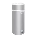
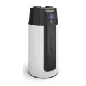
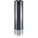
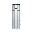
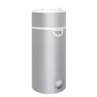
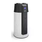
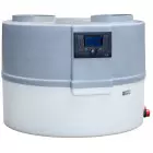
DROPS Air-to-Water Heat Pump
The air-to-water heat pump is designed for heating domestic hot water (DHW). The rotary compressor used has been optimized for condensation at high temperatures, meaning high DHW temperatures. Airflow through the heat exchanger is forced by an energy-efficient, high-performance, and modern EBM PAPST fan. Water heating takes place in a stainless steel plate heat exchanger, and water circulation is provided by a Wilo circulation pump – also suitable for potable water operation. The entire system is controlled by a controller equipped with an algorithm optimized for the design and operation of the heat pump. The housing is made of ABS plastic.


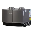
- Air outlet
- Air inlet
- Hot water outlet
- Cold water inlet
- Control panel
- Air outlet
- Air inlet
AIR DRAWN FROM ONE ROOM AND EXHAUSTED INTO ANOTHER ROOM

AIR DRAWN FROM A ROOM AND EXHAUSTED OUTSIDE THROUGH A WALL

AIR DRAWN FROM OUTSIDE THROUGH A WALL AND EXHAUSTED OUTSIDE THROUGH A WALL

AIR DRAWN FROM OUTSIDE THROUGH A WALL AND EXHAUSTED OUTSIDE THROUGH THE ROOF

SEPARATION OF SUPPLY AND EXHAUST AIR

HEAT PUMP OPERATING WITH A HEAT RECOVERY UNIT

The heat pump and the heat recovery unit operate independently, so the ventilation ducts should also be separated. This ensures that when the heat recovery unit is running but the heat pump is not, air flows freely to the ventilation exhaust and not into the heat pump. Otherwise, it would reduce the efficiency of the heat recovery unit’s fan.
| Application range | Inlet air temperature: 20°C | Inlet air temperature: 35°C | |
| Outdoor temperature | min/max [°C] | +5 / +43 | +5 / +43 |
| Maximum DHW temperature with heat pump | °C | 60 | 60 |
| DHW temperature with electric heater | °C | 75 | 75 |
| Minimum installation area | m² | 1 | 1 |
| Heat transfer medium | - | Water | Water |
| Electrical parameters | |||
| Electrical supply | - | 1/N/PE 220-240V/50Hz | 1/N/PE 220-240V/50Hz |
| Recommended fuse | A | C6 | C6 |
| Max. start-up current of heat pump | A | 15.2 | 15.2 |
| Max. operating current of heat pump | A | 3 | 3 |
| Fan / pump power consumption | W | 90 / max 55 | 90 / max 55 |
| Power consumption for inlet air temperature: | min 0.29 kW, max 0.560 kW | min 0.29 kW, max 0.650 kW | |
| Maximum heating capacity for inlet air temperature | 1.98 kW | 2.57 kW | |
| Average heating capacity for inlet air temperature and DHW heating 10-60°C: | 1.49 kW | 1.9 kW | |
| COP, water heating 10 ÷ 40°C: | 4.33 | 6.9 | |
| COP, water heating 10 ÷ 45°C: | 3.98 | 6.6 | |
| COP, water heating 10 ÷ 50°C: | 3.55 | 5.7 | |
| COP, water heating 10 ÷ 55°C: | 3.22 | 4.9 | |
| Heating time for 100 L water 10 ÷ 40°C: | 2h:30min | 1h:30min | |
| Heating time for 100 L water 10 ÷ 45°C: | 3h:12min | 1h:54min | |
| Heating time for 100 L water 10 ÷ 50°C: | 4h:00min | 2h:36min | |
| Heating time for 100 L water 10 ÷ 55°C: | 4h:42min | 3h:24min | |
The above COP values and heating times were determined under the following conditions: inlet air temperature 20°C / 35°C. Pump connected directly to the water tank. Air drawn directly from the room. In different conditions, the values given above may change.


| Refrigeration circuit | ||
| Compressor type | rotary | |
| Compressor oil type | ATMOS-RB68EP/FVC68D Quantity: 320 ml ±20 | |
| Refrigerant / quantity | type / kg | R134a / 0.6 kg |
| Max. allowable pressure (low pressure) | bar | 7 |
| Max. allowable pressure (high pressure) | bar | 23 |
| Dimensions | ||
| Diameter | Ø mm | 661 |
| Height | mm | 563 |
| Weight | kg | 45 |
| Heating circuit parameters | ||
| Heating circuit connection fittings | inch | 2xGW 3/4" |
| Minimum internal pipe diameter | mm | 20 |
| Flow rate | m³/h | 0.280 |
| Working medium | - | water / propylene glycol |

Data sheet
| Class | A |
| Weight [ kg ] | 45 |
| Height [ mm ] | 563 |
| Exhaust gas pipe size [ mm ] | 200 |
| Diameter [ mm ] | 661 |
| Outlet and inlet supply size [ inch ] | 3⁄4'' |
| Installation | Horizantal, Floor, Internal |
| Steering | CUW pump |
| Mains voltage [ V ] | 230 |
| Warranty | 2 years |
| Colour | White |
ℹ️ Viewed reviews are moderated. We do not verify that they come from customers who have purchased the product.
Reviews about The heat pump for DHW heating 2,5 kW DROPS M4.1 (0)
8 other products in the same category:
-
Heat pump for DHW - INOX EDEL (stainless steel)
-

Heat pump air-water Galmet BASIC 270 L with 1 coil
-

Heat pump air-water Galmet BASIC 270 L with 2 coils
-
Heat pump air-water Galmet BASIC 300 L with 1 coil
-
Heat pump air-water KROMMLER with stainless steel storage 300 L
-
Heat pump air-water Hewalex PCWU 3,0kW
-

Heat pump air-water Hewalex PCWU 200/ 300eK-2,5kW
-
The heat pump for DHW heating 4,1 kW DROPS M4.2