Selling since 1984 
No products
Product successfully added to your shopping cart
There are 0 items in your cart. There is 1 item in your cart.
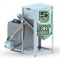
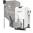
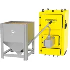
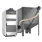
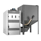
Pellets Boiler ATMOS D 14P - 14 kW


Ecological and fully automatic pellet boilers ATMOS
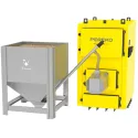
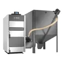
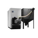
Boilers are designed in such a way that the burner is built into the left or right side of the boiler, functioning as a heat exchanger, which draws pellets from the storage tank by means of a screw conveyor. The fuel tank is located next to the boiler or in an adjacent room and can be of any arbitrary size (the standard size is 250, 500 or 1000 l). A part of the boiler room can be used for storing pellets before conveying into burner.
Burner operates fully automatic. The burner itself operates as follows. If the burner is triggered (the need to heat arises), the conveyor gets pellets into the burners spout and ignites them using a glowing coil. Following sufficient pellet combustion, the burner is adjusted to the set output where it remains until the system is heated. Thereafter, the burner is switched off and pellets in the burners chamber are burnt out. The whole cycle is repeated again when heating is required.
The boiler output and other burner functions are controlled electronically, which enables an adaptation of the boiler operation to specific system conditions. Addition of fuel, cleaning of the burner combustion chamber and removal of ash is performed once every 1 - 14 days, depending on the quality of pellets. You can add to the boiler automatic ash remover which assures even more comfortable operating.
Make sure to choose "Feeding screw" from "Available options" before putting product to the cart.
Advantages of pellet boilers ATMOS
- High comfort of heating
- high efficiency 90 % - 93 % depending on type of pellets – low consumption of fuel
- Ecological burning - boiler class 5 - ČSN EN 303-5, ECODESIGN 2015/1189
- Automatic operation and swich off the boiler after the fuel burns out
- Automatic ash removing – in case of installing with ash remover
Pellet burner ATMOS A25
Specified fuel: good quality pellets with 6 – 8 mm diameter, 5 - 25 mm lenght and 16 - 19 MJ.kg-1 caloric power (white pellets).
The burner screen: used to display the current status of the burner and adjusting her functions
Burner control: with an AC07X (AC07) electronic control unit that controls the operation of the external conveyor, two ignition spirals and the fan in accordance with requirements of the boiler and the heating system. The electronic system is protected with the safety thermostat of the boiler, safety thermostat at the pellet supply to the burner, the fan speed transducer and the flame sensing photocell. The operation of the burner is indicated on the electronic control display.
Fuel feeding: with an external auger conveyor controlled from electronic regulation of burner.
Basic functions of burner:
The possibility of using two spare outputs R and R2 for various applications
The possibility of the involvement of four different sensors TS, TV, TK a TSV
TS - sensor on the tank bottom
TV - sensor on the tank top
TK - boiler sensor or middle sensor on the tank
TSV - flue gas sensor or solar panel sensor
- burner controlling it in accordance with two temperatures (sensors) on the buffer tank
- control of boiler fan from burner with the help of the auxiliary output
- control of boiler pump from burner with the help of the auxiliary output
- control of the solar system directly from the burner
ℹ️ Viewed reviews are moderated. We do not verify that they come from customers who have purchased the product.
Reviews about Pellets Boiler ATMOS D 14P - 14 kW (0)
23 other products in the same category:
-

Boiler Tekla DRACO BIO 12kW-75kW
-

Boiler Tekla DRACO BIO 100 - 150
-

Boiler Metal-Fach SLIM PELLET MINI
-

Boiler STALMARK PELLET VEGAS II 10-35 kW
-

Boiler STALMARK PELLET VEGAS 45-80 kW
-

Boiler Tekla DRACO D BIO
-

Boiler for pellets PEREKO QmPell Evo 12 - 18 kW
-

Automatic pellet boiler Tekla CLASSICO BIO
-
Pellet Boiler PEREKO PELL-STAR 18 kW
-

Boiler Tekla DRACO BIO COMPACT FII GP
-

Boiler for pellets DEFRO Komfort Ekopell
-

Boiler for pellets Defro Delta EkoPell
-

Boiler for pellets Defro Smart EkoPell
-

Boiler for pellets Defro Kompakt EkoPell F
-
Pellet Boiler PELL-STAR PRO 130–160 kW
-
Boiler Metal-Fach SEG PELLET 60 kW
-
Boiler Metal-Fach SEG PELLET 75-100 kW
-

Boiler Metal-Fach GRAND PELLET 50 - 150 kW
-

Boiler Metal-Fach GRAND PELLET 200 kW
-

Boiler Metal-Fach GRAND PELLET 300 kW
-

Boiler Metal-Fach GRAND PELLET 400 - 500 kW
-

Boiler for pellets EG-PELLET MINI
-

Pellet boiler EG-MULTIFUEL P 80 - 600 kW